Capacitor Polarity Identification Guide for SMD and Through-Hole Components in the Supply Chain
In electronics manufacturing, repair, and distribution, correct capacitor orientation is more than a detail — it’s a safeguard for product reliability. Reversing a polarized capacitor can lead to premature failure, reduced lifespan, or even safety risks. For professionals in the electronic components industry, knowing how to read polarity quickly and accurately is an essential skill. At ICHOME, we help our partners avoid costly assembly errors by ensuring all polarized capacitors are supplied with clear, verifiable markings.
1. Polarized vs. Non-Polarized — The Foundation
Every capacitor belongs to one of two categories:
-
Non-polarized types: These include multilayer ceramic capacitors (MLCCs) and most film capacitors. They function correctly regardless of mounting direction.
-
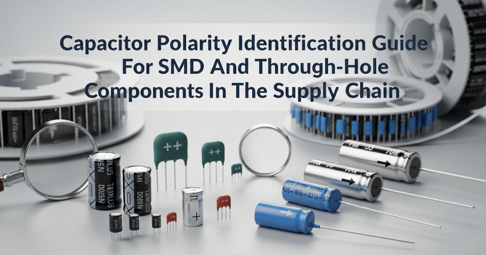
Polarized types: Aluminum electrolytic, tantalum, conductive polymer (aluminum or tantalum), supercapacitors/EDLCs, and lithium-ion capacitors must be installed in a specific orientation. Incorrect polarity can cause electrical leakage, excessive heat, or device failure.
For procurement teams, identifying the type during incoming inspection helps prevent incorrect part usage in SMT and through-hole processes.
2. Recognizing Polarity in Different Packages
Radial and Axial Aluminum Electrolytics
-
Negative terminal: Shown by a contrasting stripe on the sleeve.
-
Positive terminal: Often the longer lead on unused components.
-
Axial designs may have arrows pointing toward the negative lead.
SMD Aluminum Electrolytics
-
Negative side: Indicated by a stripe or painted segment on the top cover.
-
Some models feature a base notch aligned with the negative pad.
Molded Tantalum Chip Capacitors
-
Positive terminal: Identified by a printed bar or “+” symbol.
-
This marking style is opposite to aluminum electrolytics, which is a frequent source of assembly mistakes.
Leaded Tantalum Capacitors
-
Longer lead = positive, shorter lead = negative.
-
Positive end may also have a “+” printed directly on the body.
Conductive-Polymer Capacitors
-
Aluminum polymer can: Stripe marks the negative lead.
-
Tantalum polymer block: Bar or “+” marks the positive lead.
Supercapacitors & Lithium-Ion Capacitors
-
These devices are polarized. The negative side is marked with a stripe or “−” symbol, and reverse connection is strictly prohibited.
Film Capacitors with “Outside Foil” Bands
-
The band indicates the lead connected to the outer foil for noise reduction, not polarity.
3. Common Errors We See in the Industry
-
Mixing tantalum and aluminum rules
-
Aluminum electrolytic: Stripe = negative.
-
Tantalum: Bar or “+” = positive.
-
-
Judging solely by lead length
-
Leads may be trimmed in kitting or rework. Always verify with markings.
-
-
Ignoring supercapacitor polarity
-
Even with high current capacity, EDLCs cannot tolerate reverse voltage.
-
-
Reading outer foil bands as polarity
-
This only applies to shielding orientation in film capacitors.
-
4. Process Recommendations for Industry Professionals
To minimize the risk of assembly issues:
-
At the distribution stage: ICHOME cross-references polarity data with manufacturer datasheets before shipping.
-
At incoming quality control: Use marking charts and sampling to confirm orientation.
-
Before PCB assembly: Ensure the CAD footprint and silkscreen match the part’s marking style.
For high-volume projects, ICHOME offers custom polarity reference guides tailored to specific part numbers. These resources streamline AOI setup and operator training.
5. Quick-Check Workflow
-
Identify the capacitor category — ceramic, film, aluminum electrolytic, tantalum, polymer, or supercap.
-
Locate the orientation mark — stripe/paint for negative (most aluminum types), bar/“+” for positive (tantalum types).
-
Confirm with datasheet if uncertain.
-
Cross-check PCB markings before soldering.
6. ICHOME’s Value to Your Operations
Our responsibility as a distributor is to protect your production line from preventable errors. That’s why we:
-
Ship only verified components with polarity markings confirmed against datasheets.
-
Provide supplementary packaging labels indicating correct orientation.
-
Include polarity confirmation in Certificates of Analysis (COA) for traceability.
-
Offer training and documentation so assembly teams can identify polarity at a glance.
By incorporating polarity verification into our quality control process, ICHOME helps customers reduce rework rates, maintain production efficiency, and ensure every device shipped meets its reliability targets. This approach strengthens your supply chain and protects your reputation in the market.